Here Comes Class 4 Power: Differences Between Circuit Classes
페이지 정보
작성자 Leticia McCorki… 댓글 0건 조회 12회 작성일 25-05-29 19:25본문
The magnetic field in a waveguide is made up of magnetic lines of pressure that are caused by current movement by means of the conductive materials of the waveguide. Magnetic strains of pressure, called H traces, are continuous closed loops, as shown in determine 3-25. All the H traces related to present are collectively referred to as a magnetic area or H area. The reflection of a single wavefront off the "b" wall of a waveguide is shown in figure 3-31. The wavefront is proven in view A as small particles, In views B and C particle 1 strikes the wall and is bounced back from the wall without shedding velocity. The forward-progress velocity of the wavefront in a waveguide known as GROUP VELOCITY and is somewhat slower than the speed of gentle. The other can also be true; rising frequency will increase the group velocity. The group velocity of power in a waveguide is set by the reflection angle of the wavefronts off the "b" partitions. The distinction is that the vitality in a waveguide is confined to the physical limits of the guide. This severely limits the bandwidth, effectivity, and application of the sort of two-wire line.
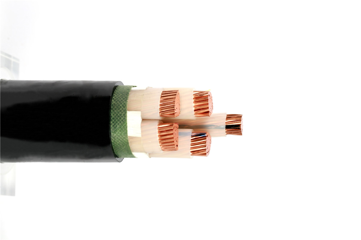
 A shielded cable is a type of cable that has a metallic shield across the conductor. The cable meets the GB/T 12706, IEC 60502, and related home and foreign requirements equivalent to BS, VDE, JIS, AEIC, and so on. The maximum allowable long-term operation temperature of the cable conductor is 90℃, and the ambient temperature for cable laying shouldn't be lower than 0℃. The packaging specifications could be personalized in line with your necessities. An electric discipline Cannot exist parallel to a perfect conductor. Electromagnetic energy transmitted into house consists of electric and magnetic fields which can be at right angles (ninety degrees) to one another and at proper angles to the path of propagation. Since vitality is transferred via waveguides by electromagnetic fields, you want a fundamental understanding of area theory. So far, solely essentially the most fundamental sorts of E and H subject arrangements have been shown. This fundamental precept is illustrated in figure 3-33. As frequency is decreased. The primary boundary condition (illustrated in fig.
If a system satisfies one of these boundary conditions, it should additionally fulfill the other since neither subject can exist alone. For a various magnetic discipline to exist, it must form closed loops in parallel with the conductors and be perpendicular to the electric discipline. The magnetic area in a rectangular waveguide is within the type of closed loops parallel to the floor of the conductors. A part of the magnetic area is parallel to the size axis. In the transverse magnetic (TM) mode, all the magnetic discipline is in the transverse aircraft and has no portion parallel to the size axis. In the circular waveguide in figure 3-39, the E subject is perpendicular to the size of the waveguide with no E traces parallel to the direction of propagation. The best place to locate the probe is in the center of the "a" wall, parallel to the "b" wall, and one quarter-wavelength from the shorted finish of the waveguide, as shown in figure 3-41, Views B and C. This is the point at which the E discipline is most within the dominant mode. Such an insulator is shown in determine 3-20. The impedance of a shorted quarter-wave part is very excessive at the open-finish junction with the 2-wire transmission line.
 A greater high-frequency insulator is a quarter-wave part of transmission line shorted at one finish. When a small probe is inserted into a waveguide and equipped with microwave vitality, it acts as a quarter-wave antenna. When the post or screw extends fully through the waveguide, making contact with the top and backside walls, it acts as an inductive reactance. An inductive iris and its equal circuit are illustrated in figure 3-44, View A. The iris places a shunt inductive reactance throughout the waveguide that is instantly proportional to the size of the opening. The traces grow to be a part of the walls of the waveguide, low voltage power cable as illustrated in determine 3-22. The vitality is then conducted inside the hollow waveguide instead of alongside the two-wire transmission line. The design of a waveguide is set by the frequency and power degree of the electromagnetic power it will carry. Waveguides are usually designed so that solely the dominant mode will probably be used.
- 이전글Poker Bonuses - Does Size Matter? 25.05.29
- 다음글Fertility Vitamins & Supplements To Extend Pregnancy Odds 25.05.29
댓글목록
등록된 댓글이 없습니다.
